INTRODUCTION
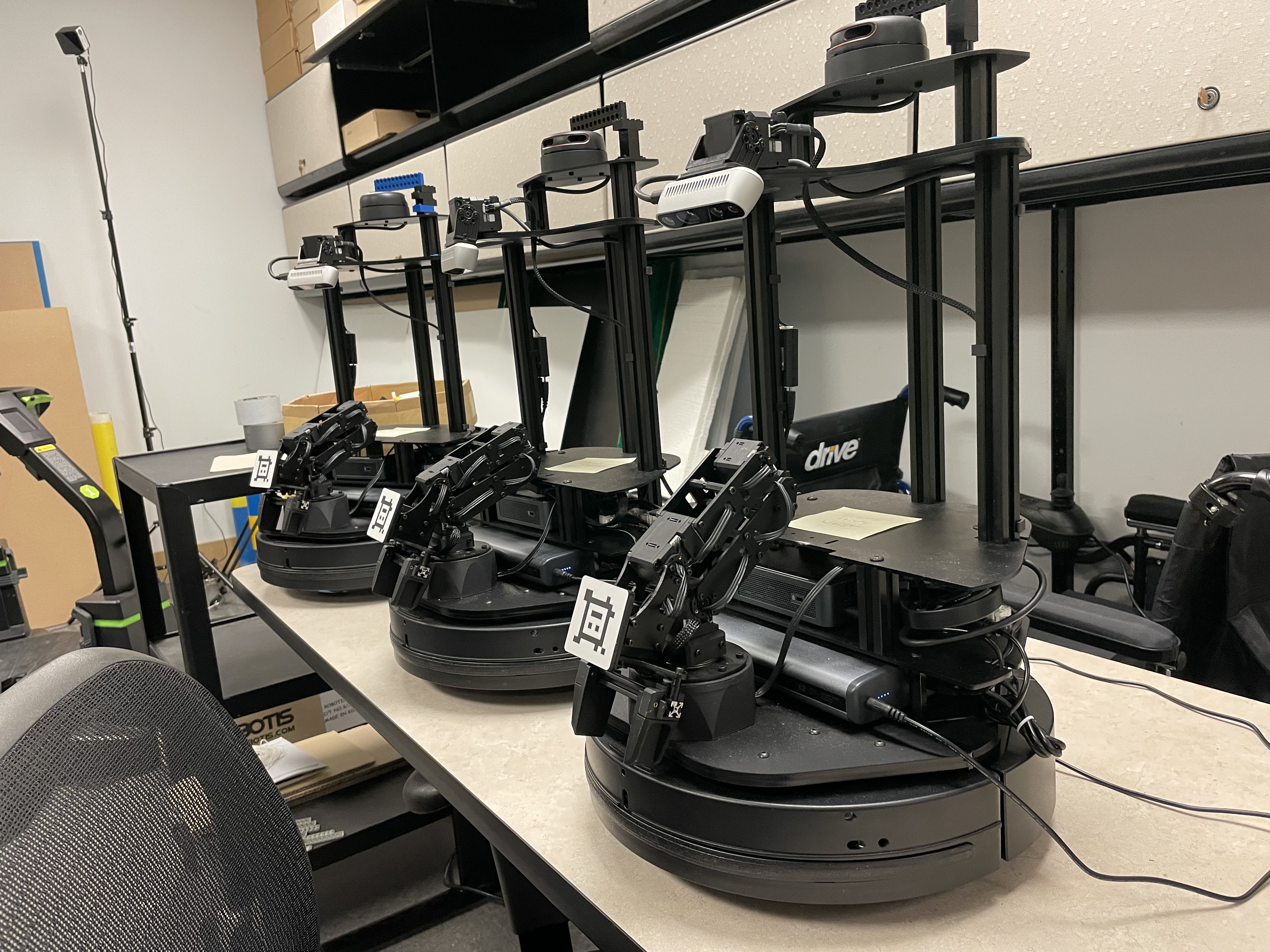
This project was done as a part of the CS685 Autonomous Robotics course at George Mason University. We were interested in experimenting with a real robot and ROS, and therefore chose to work with the LoCoBot PX100. We chose a "toy" problem of a block collecting robot that incorporates the concepts of Inverse Kinematics, Control, Probabilistic Robotics, Mapping and Localization, and Perception that were taught in the course, to let a robot navigate through and interact with the environment to perform basic tasks. The project was developed using ROS Noetic, which the LoCoBot supports seamlessly.
This tutorial is an informal introduction to using the LoCoBot and a walk through of each of the components that make up our project. We'll also discuss some practical tips and the challenges we faced. The LoCoBots offer a variety of sensors and capabilities that are very accessible to beginners, students, and researchers. We only scratched the surface of what is possible. We hope that sharing our experience through this tutorial will assist future students in leveraging the GMU Autonomous Robotics Lab's fleet of LoCoBots. We look forward to the cool projects to come!
warning Warning: You will have a ton of fun working with a real robot. It will also take a lot more time than you think and be full of unexpected challenges. Be prepared for some long days and late nights! We highly recommend breaking your project down into distinct subgoals and make incremental progress. Be ambitious, but have a plan and get started right away.
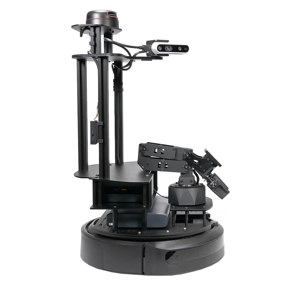
LOCOBOT PX100
- Kobuki Base from Yujin Robot (YMR-K01-W1)
- Intel NUC NUC8i3BEH Mini PC
- Intel RealSense Depth Camera D435
- PincherX 100 Robot Arm (4 degrees of freedom)
- RPLIDAR A2M8 360° Laser Range Scanner
- MoveIt Support
QUICK GUIDE
The LoCoBots we used are hosted by the GMU Autonomous Robotics Laboratory, and configured by Michael Schader. Some of the information here on getting started is installation dependent and may change overtime.
To start the LoCoBot, you will need to power on both the base (toggle switch on the side) and the onboard Mini PC located under the frame (push button, lights up blue). The rechargeable on board power supply provides plenty of charge for a few hours of use. Once the PC is powered on, the accompanying laptop computer can be used to SSH wirelessly to the onboard PC. Must be connected to the MASON network in the lab (not MASON SECURE). Each LoCoBot is numbered, so the for example, ssh locobot04.
The Locobot PCs are running on Ubuntu 20.04 focal and are already configured to start development. We recommend creating your own directory for your files. There are several ROS nodes that need to be launched to operate the Locobot, but these can be easily stopped and started via aliased daemon scripts. Run one of the following:
sam - "Mobile" mode, the standard operationsas - "Stationary" mode, disables base operations (maybe you need to work on a table)saj - "Joystick" mode, control with a PS4 controller. This is fun and gives you a feel for how the robot handles!
To terminate, run sa in the same terminal window. You may need to repeat and should get confirmation the processes have stopped. The LIDAR spin is a useful indicator of the state as well as the base chimes.
Interbotix provides a locobot.py module with the InterbotixLocobotXS class. If everything is running you can start controlling right away by importing this module and calling the API commands. Michael Schader created a simple bash script that runs a Python shell with the class loaded (located at ~/mds-locobot/scripts/python3.sh):
                python3 -ic 'from interbotix_xs_modules.locobot import InterbotixLocobotXS

                locobot = InterbotixLocobotXS("locobot_'${LOCOBOT_MODEL}'", "mobile_'${LOCOBOT_MODEL}'")'
You can now start driving. Here's a simple API command to drive forward .2 m/s for 2 seconds:
locobot.base.move(.2,0,2)Now let's rotate. This will rotate counterclockwise for 1 radian/second for two seconds. In your code we recommend using math.pi in your angular velocity units and pose angles.
locobot.base.move(0,1,2)
And of course you can combine both and go backwards, clockwise:
locobot.base.move(-.2,-1,2)
Now let's move the arm. There are two preset poses:
locobot.arm.go_to_home_pose()locobot.arm.go_to_sleep_pose()
To use MoveIt to plan a trajectory and execute a successful one, use locobot.arm.set_ee_cartesian_trajectory() providing the x, y, z values. When in home pose, x, y, z are all 0. Play around with the values to find which plans work and what positions are reachable.
Always make sure the arm is in the sleep pose before terminating the processes. The torque will stop, causing the arm to fall if not at the sleep pose.
The functions locobot.gripper.open(), locobot.gripper.close() can be used to open and close the end-effector of the arm.
The function locobot.base.command_velocity() could be used to move the robot, and check how much the robot thinks it moved using locobot.base.get_odom() that provides the (x, y, yaw) with respect to the origin. The origin is the position where the robot initiates or can be manually set using locobot.base.reset_odom().
To tilt the camera, pass an angle in radians to this function. 0 is parallel to the ground, positive angles are towards the ground.
locobot.camera.tilt(.5)
Interacting with the Interbotix Locobot API in a shell is a great way to discover other functions and get a feel for how to control. We recommend taking some time to manually direct the robot via the shell to see what is possible. You can wrap a function around the Python help() function to get more information, or consult the Interbotix documentation.
- Rosboard is a great dashboard to explore all the available ROS topics their published data in realtime. It is accessbile at http://locobot04:8888 (replace 04 with your Locobot number). Of particular use is the
/tag-detections-image, which will display the current camera frame and any AprilTags detected. We used this very often. - Rosbag is an essential tool that can record and playback specified topics. This was very helpful both for troubleshooting and developing the Localizer code offline in a VM. We wrote a bash script to record the topics we needed. Don't do all the topics, as the camera ones take up a lot of space.
- When in motion, a validation is added to check if the base bumper hits anything to stop the motion (no rogue robots!). Easy way to command a halt without killing the script
- The topic
/scancan be used to get the LIDAR readings. - Navigation Stack provides many rich features and mapping visualization. LoCoBot needs to be connected to a monitor for visuals in Rviz. We wish we had more time to play around with this!
- It is possible to SSH to the GMU Locobots from a personal laptop (though we only got a Mac to work). Ask Michael, us, or one of the lab faculty.
- VS Code is great for development and offers a ROS extension and supports step debugging. Setting Remote Development using SSH in VS Code could save lots of time!
- The topic
/scancan be used to get the LIDAR readings. - Create log files and log any raw data for calculations, so that after a run it's easier to analyze the log files for issues in calculations.
- Make a plan (preferably with subgoals) and implement the subgoals as individual functions. This is better for modularity, maintenance, testing, and debugging.
- Having detailed logging is essential for debugging. Direct your outputs to log files rather than the terminal.
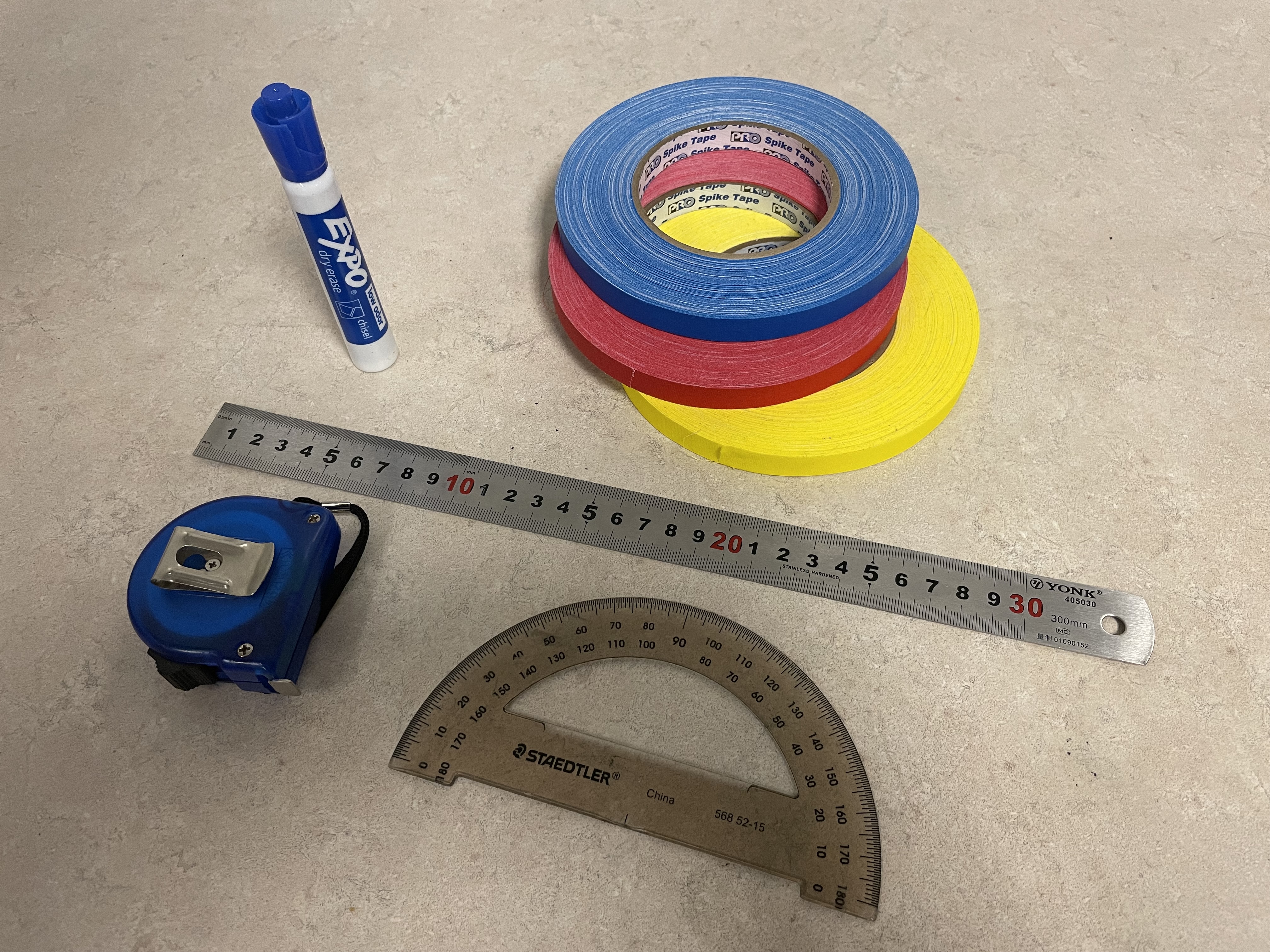
- The supplies shown in Fig. 1 were super handy while working on the project. Colored spike tape, commonly used in theater, is particularly helpful for marking the ground (full disclosure: Aaron's wife works for Barbizon)
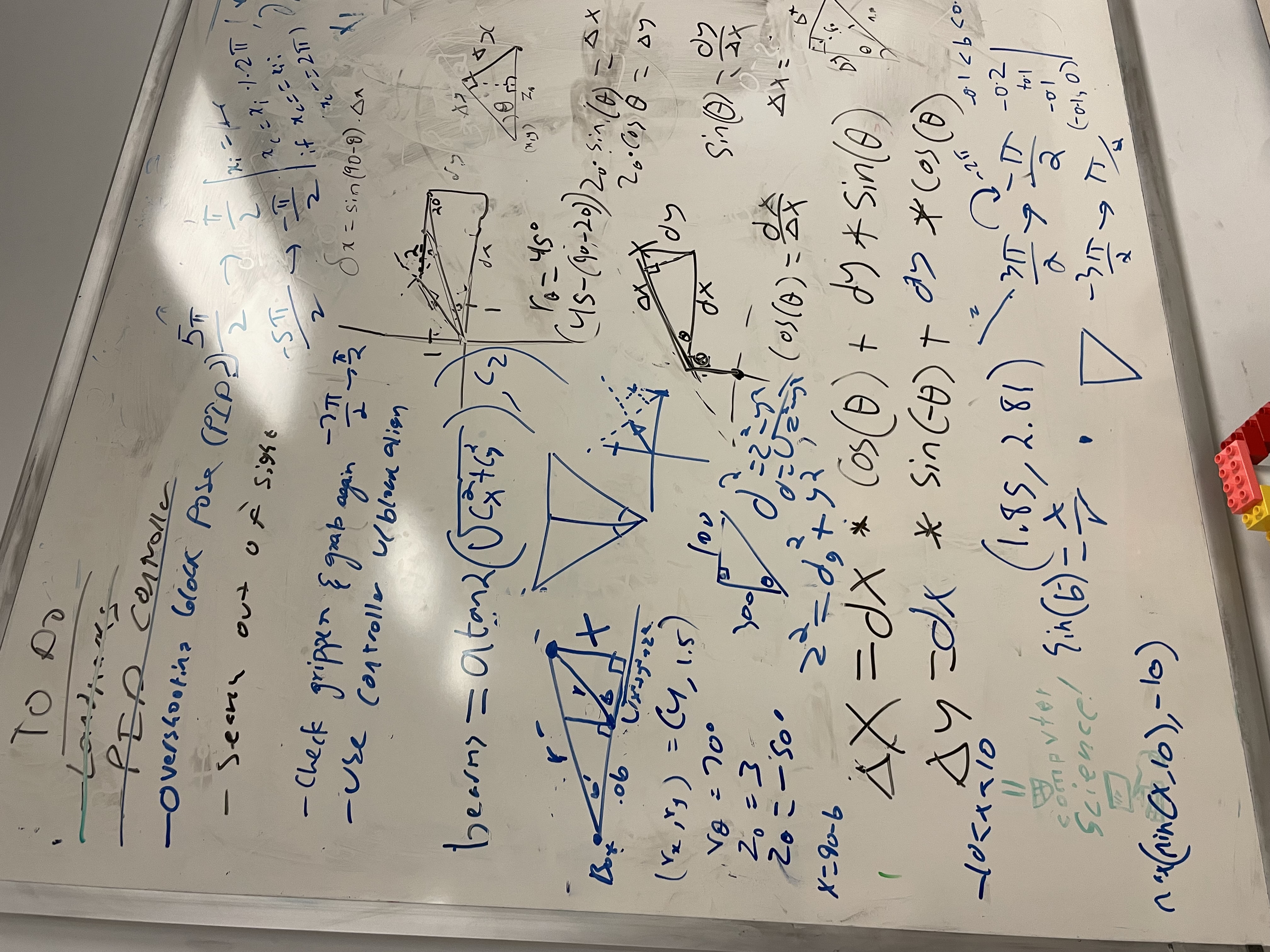
- Definitely, have a whiteboard in your workspace. Always helps writing down what's going on (don't ask what's on our board)
PROJECT OBJECTIVE - TOY COLLECTION
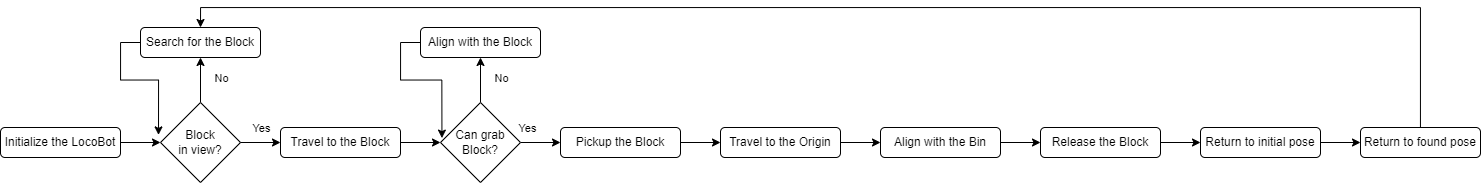
The complete goal of the problem is for the robot to search for a block using its AprilTag, travel to almost near the block using Landmark SLAM, pickup the block using Inverse Kinematics, travel back to the origin, and drop the block into the bin.
Project Structure
The main project file is blockbot.py. Our BlockBot class inherits from InterbotixLocobotXS, therefore the Locobot API is available to us as class methods and we can implement our own higher level logic. The method execute_sequence() starts the state sequence above.
Similar to Michael's shell script, we implemented blockbot_shell.sh to instantiate our BlockBot class and run commands. It was convenient to be able to re-run or experiment as needed. The script also redirects the Python output to a log file.
APRILTAG
In this project, AprilTags were used to identify the block and the landmarks. This is a useful project simplification to avoid computer vision tasks such as camera depth perception and object detection (which could be a project all on its own), as well as the error those could introduce.
The /tag_detections topic provides the list of AprilTag detections. The relevant AprilTag information was extracted from this and stored in the class variables (check get_tag_data()).
The Interbotix provides an AprilTag Module to combine the camera information with the AprilTag pixel data to provide real meter values for the tag detection data.
The raw AprilTag detections provided by /tag_detections topic include the pose and orientation of the AprilTag with respect to the camera (see Fig. 5). To understand the values, let's consider the AprilTag with ID 5 (the tag on the robot arm in Fig. 4). The detections[0].pose.pose.pose has the required information, where position is the estimated position of the AprilTag and the orientation is the tilt of the tag in all dimensions with respect to the camera's field.
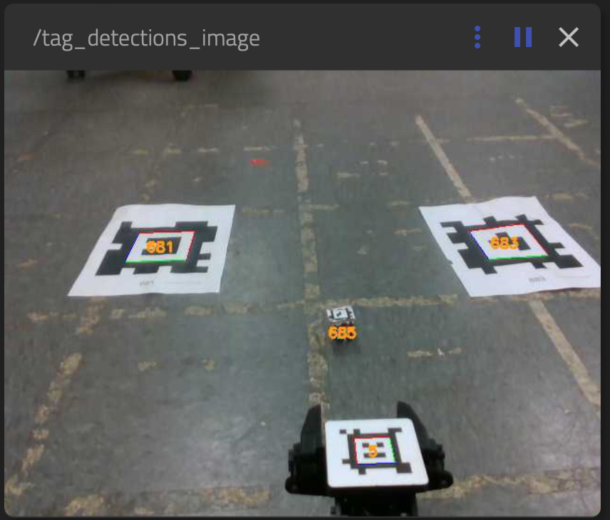
/tag_detections_image topic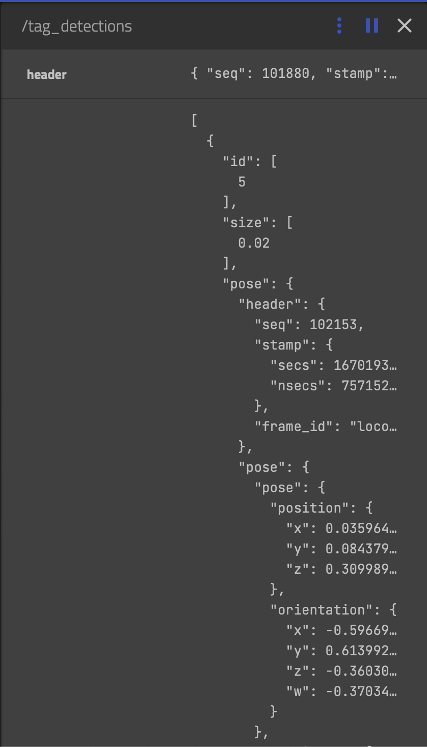
/tag_detections topic
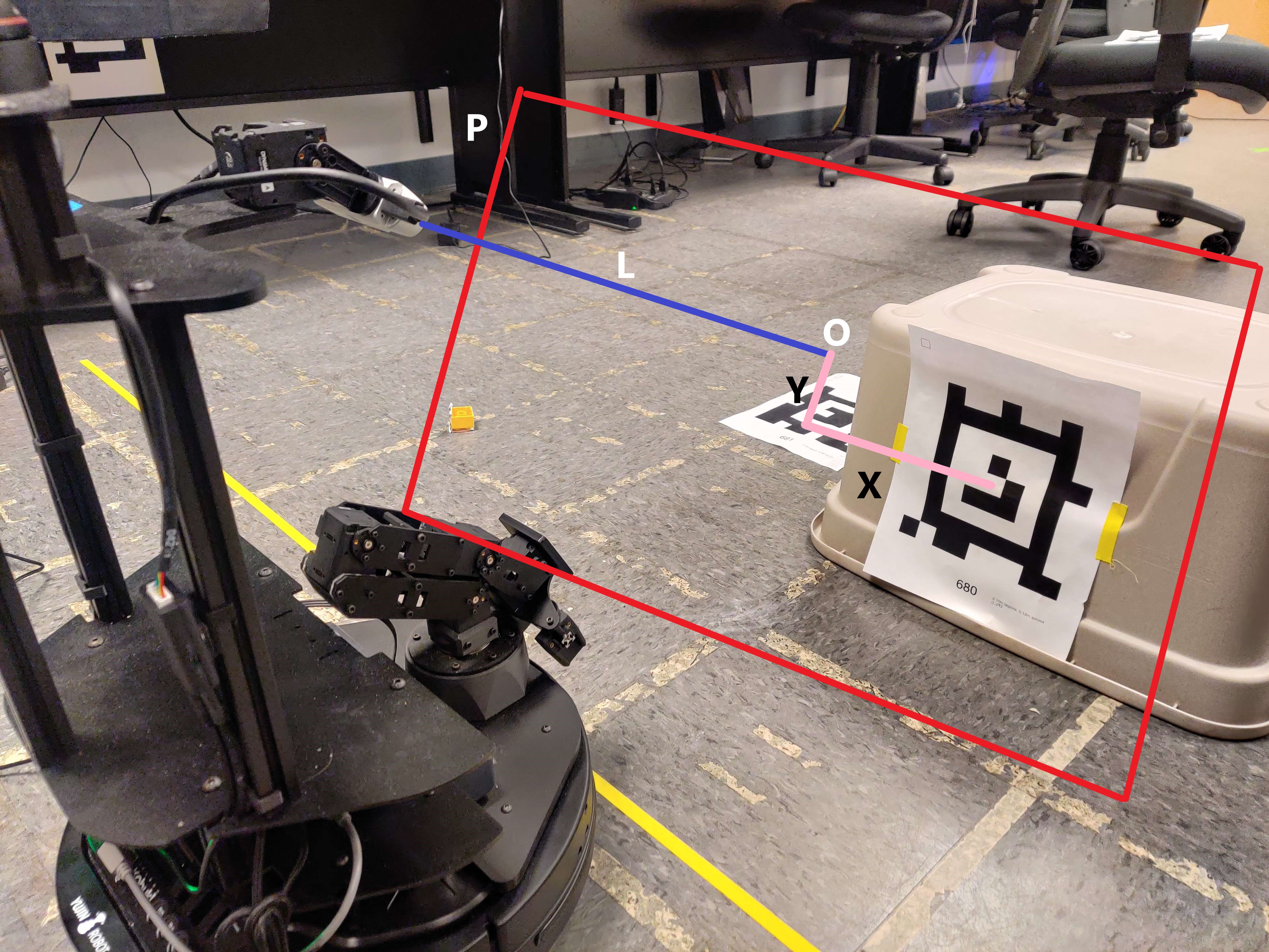
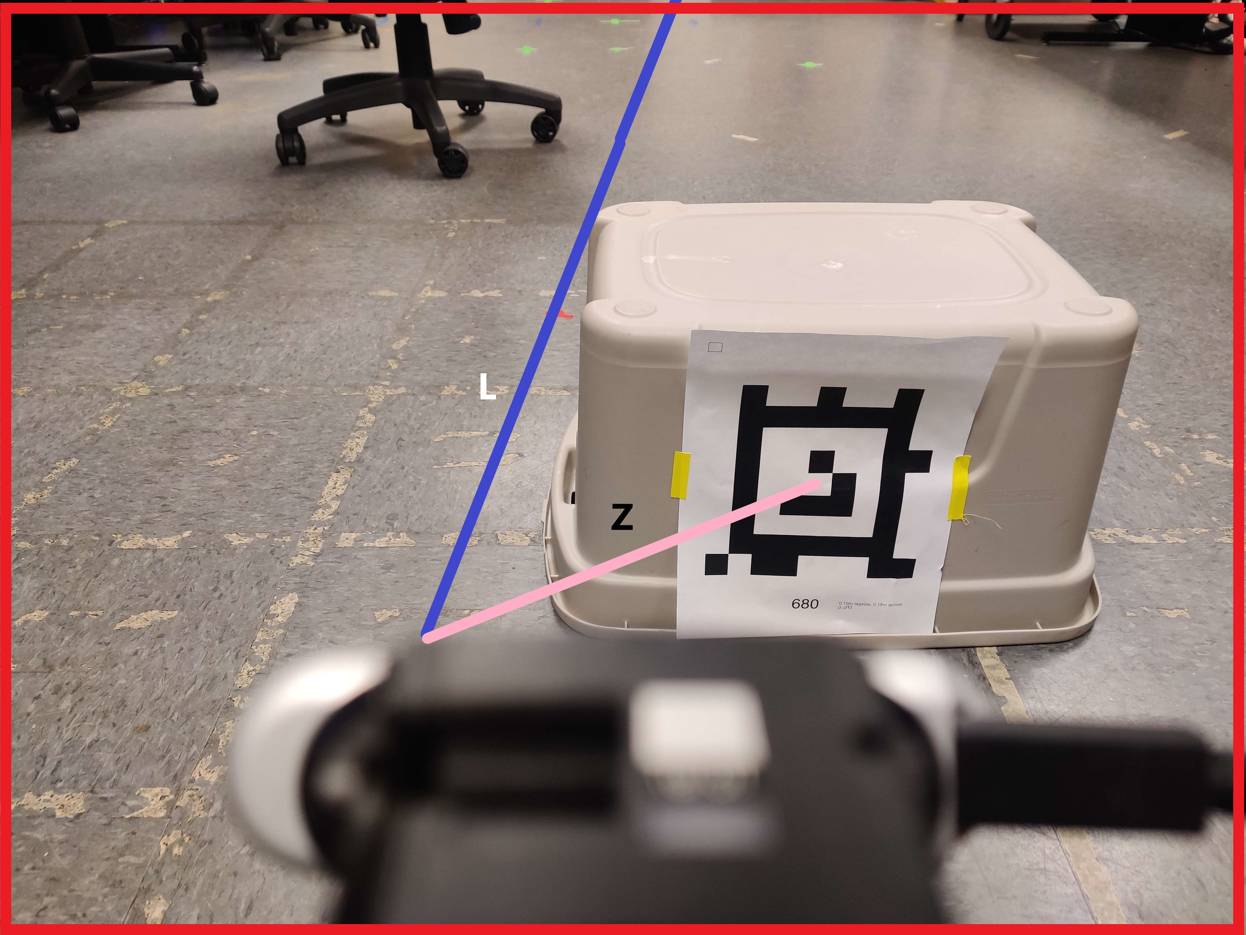
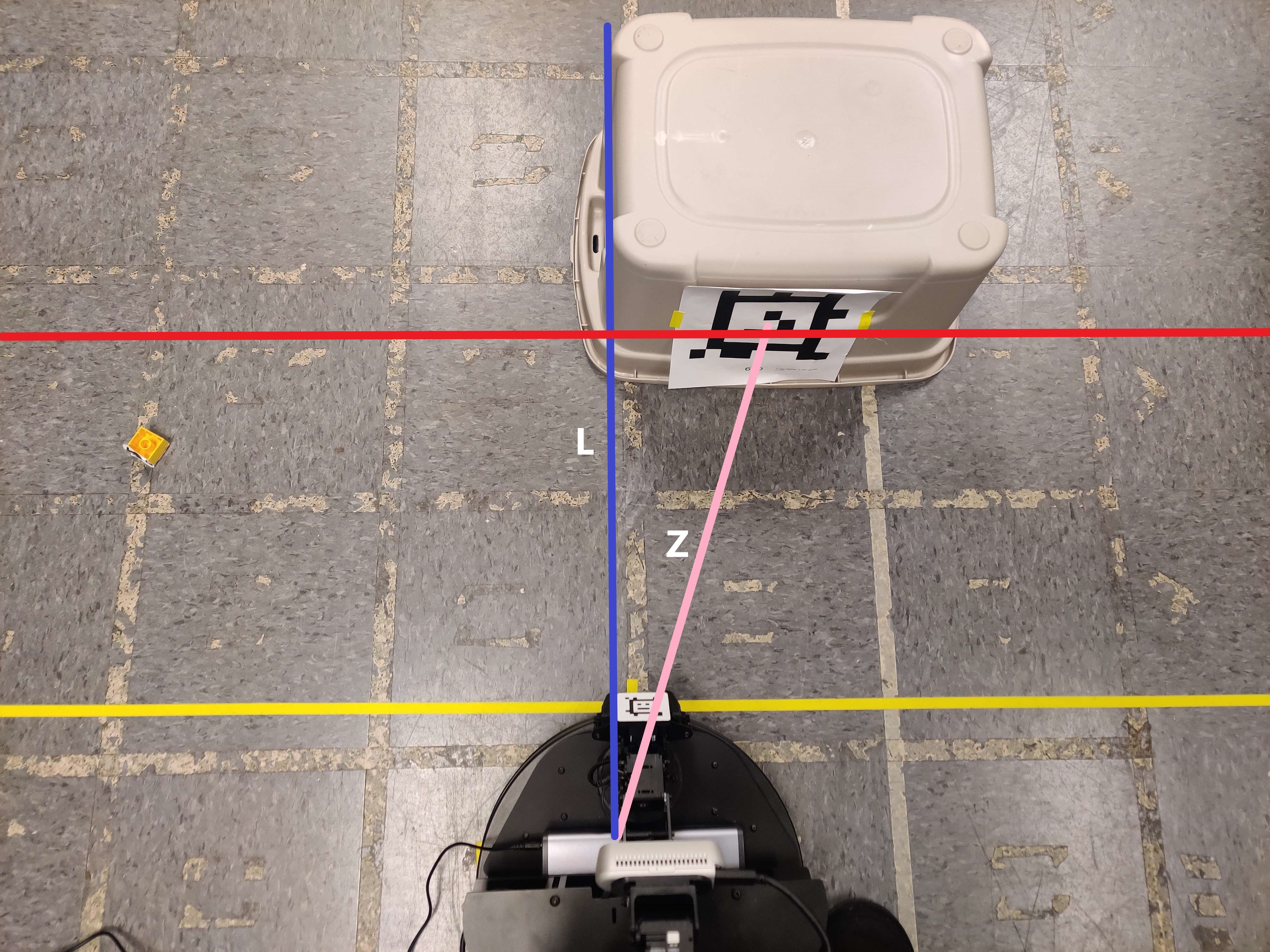
To understand the position, visualize a line L going from the center of the camera going into the 3D field of view. At the position.z (Z) distance from the camera, draw a 2D plane P (that contains the AprilTag), marking its intersection with L as the center of the plane, say O. Now, position.x (X) is the horizontal distance from the origin O (right-positive, left-negative) and position.y (Y) is the vertical distance form the origin O (top-negative, bottom-positive). The projections in Fig. 6, 7, 8 below might be helpful in understanding this.
The size seen in Fig. 5 (i.e., 0.02) is the size of the AprilTag configured in ~/mds-locobot/apriltag-files/tags.yml Any new AprilTags should be added to this file.
BEARING & RANGE
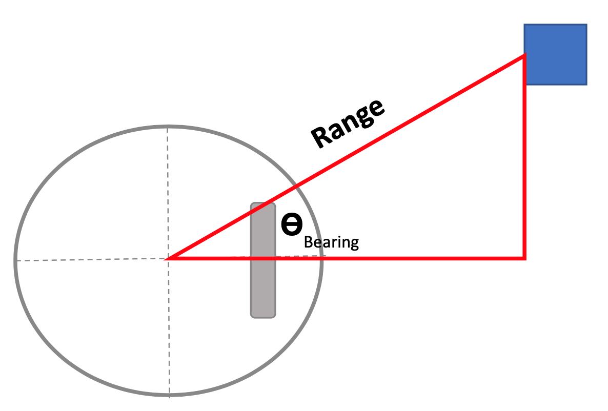
By placing AprilTags on objects or on the ground, they can be used to calculate the bearing and range from the robot's center to the center of the AprilTag. These values are always relative to the robot's pose at the time of the detection. We used this in two ways: to estimate the block's coordinates to drive close to it, and to detect relative landmark positions to aide in localization.
We use 2D odometry, however the tag's position.z value is the 3D distance to the tag's center. Therefore we need to use the position.y value to project to a line parallel to the camera. We then account for the camera tilt by rotating opposite the tilt angle. This gives us the line parallel to the ground from the camera to the tag plane. In this project we do not permit the camera to pan.
To keep the measurement inline with the odometry, we further take into account that the left camera performing the tag detections is not at the center of the robot. A combination of measurements and trial-and-error led us to the values below, though you could consider adjusting, particularly the camera_radius_offset. To handle the left camera's offset from the robot's true heading center, we can simply subtract the offset from the tag's x value (since it's in real meters).
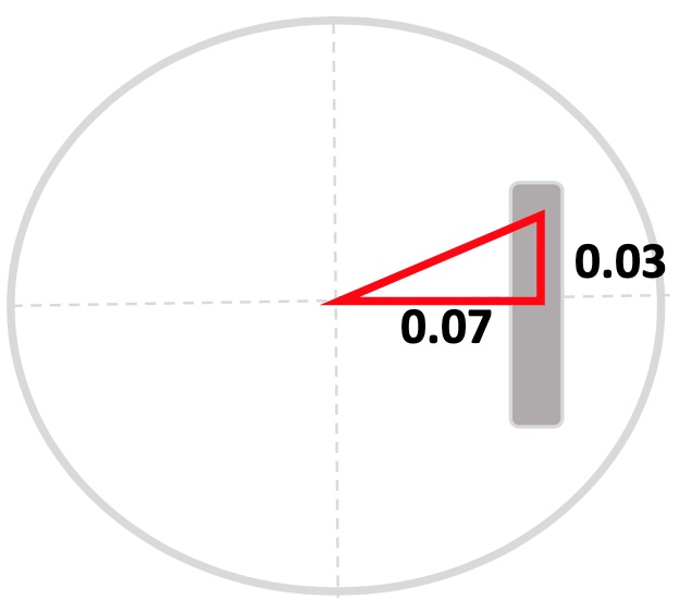
Now we need to consider that not only does the camera_radius_offset impact the true range, but also the bearing. Here is the full trigonometry problem we can solve. Since we already accounted for the camera's x offset, we can assume the camera is centered int he diagram.
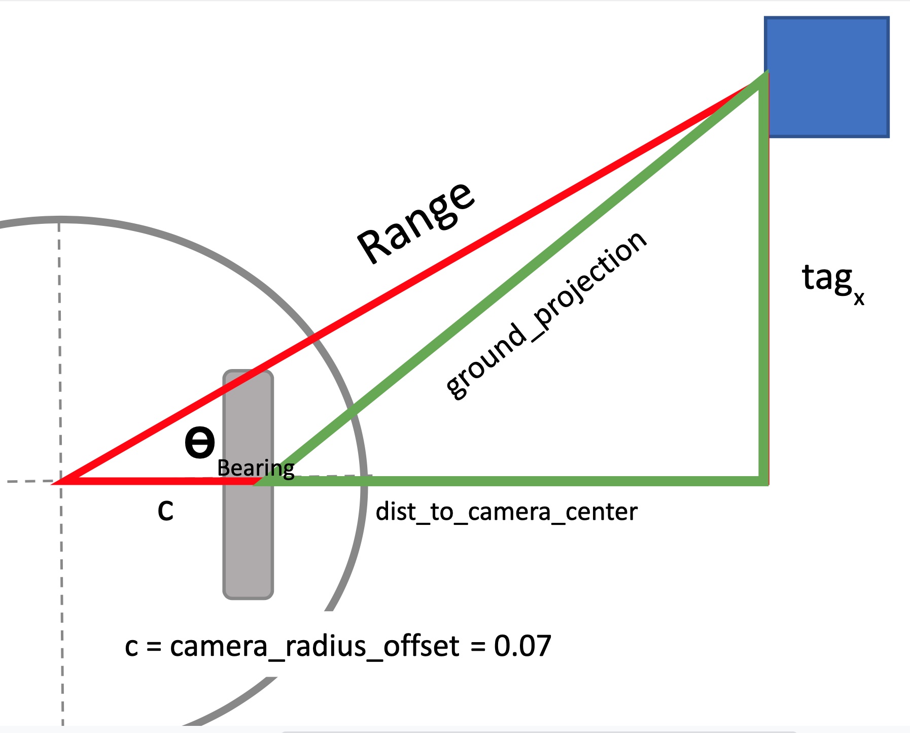
We use the tag's shifted_x value to project the ground_projection to the camera center. Imagine a line parallel to the ground that goes from the camera to the plane of the tag.
Now we can add the camera_radius_offset to get the base of the larger triangle. We can now solve for the bearing and range values.
Return the values, though since the camera is upside down we need to flip the bearing angle.
SEARCH & INVERSE KINEMATICS
The first subgoal was to search the block by rotating and grab it, when the base was stationary (see Fig. 12, 13, 14). Then the robot was certain of its location when SLAM was implemented, so we integrated motion with PID and started searching for the block outside its view. When initiated, the robot first looks for the block in its current view, then on its left, and then on its right (rotating by ROTATION_INCREMENT w.r.t origin). If the robot doesn't find the block it moves forward by SEARCH_INCREMENT_X meters. If in any of the view the robot finds the block, it travels to a point that is BLOCK_TRAVEL_RADIUS meters away from the block and starts alignment. As the robot searches in one direction, we only check left, straight, and right covering specific field only. The search code is available find_goal().
Since the LoCoBot PX100 has only 4 degrees of freedom, the arm doesn't have a wide field of reach for the end effector. So we chose to align the robot with the block so it always end up in a position that makes it easier to grab the block. For the alignment part in align_with_block(), the block is expected to be near the robot. The robot looks in the nearby field (hence the camera tilt at the beginning), and then slowly rotates or moves forward using PID controllers until the block is in [-ALIGN_BEARING_ACCEPTANCE, ALIGN_BEARING_ACCEPTANCE] and [-ALIGN_RADIUS_ACCEPTANCE, ALIGN_RADIUS_ACCEPTANCE] ranges. As PID controllers are used, the motion is inversely proportional to the distance/angle from the block, which ensures accurate alignment with the block.
To obtain these fixed distance and angle of alignment, we've experimented with multiple positions of the block and found the one that makes it easy to grab. Once aligned the grab_block() function is used to grab the block. The robot's arm is set to the home pose, and in the set_ee_cartesian_trajectory(), z is set to -0.25 which makes the arm reach the ground from the home position. At this point the block would be within the grippers range but at a little far, to account for any errors in alignment. Then the robot moves forward by GRABBING_ERROR_DISTANCE meters, grabs the block, and returns the arm to the sleep pose. This function internally uses MoveIt to check if a plan exists to reach the specified position and executes if one exists.
LANDMARK SLAM
In order to accurately travel to goal pose's, including returning back to the "home" position where the bin is located, the robot needs top track where it is. The Kobuki mobile base publishes the current odometry on the topic /locobot/odom. Conveniently Interbotix provides a get_odom() function that produces a simple 2D pose, rather than the quaternion.
Odometry by itself for localizing the LoCoBot isn't too bad, especially just driving in a straight line. However as it starts to make turns and move further, it starts to become inaccurate. We sought to demonstrate an effective use of Landmark SLAM to improve the LoCoBot's estimate of it's current pose.
Imagine you are lost driving in a city. You know where you started and roughly how far you've driven and maybe the direction you went, but not well enough to say exactly where you are (and no GPS signal!). You make a turn and suddenly see a pizza place you've driven past before, and then a gas station you previously stopped at. Now you know exactly where you are located.
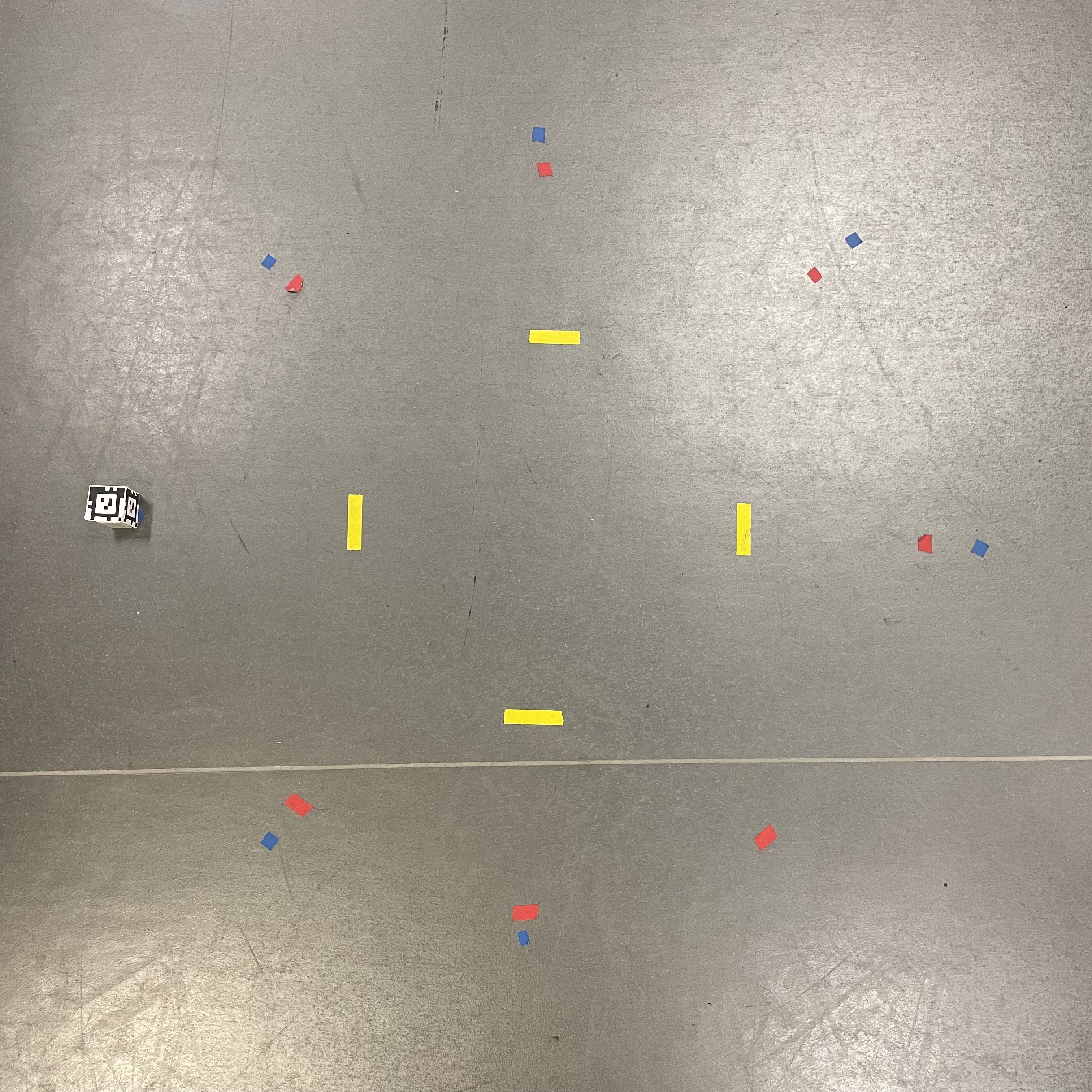
We placed four large AprilTags on the ground to serve as stationary landmarks. At every time step the robot can register what landmark tags are visible, and their bearing and range relative to the robot. For simplicity the robot always knows which landmark it is detecting via the AprilTag ID. A future project could ignore the tag ID values and experiment with performing data association of unknown landmarks.
GTSAMTo fuse together the landmark observations, the robot's odometry readings, and the potential error in both of these, we turn to probabilistic and leverage factor graphs and Bayes Networks. A formal discussion of these are outside the scope of this tutorial (see Probabilistic Robotics). The idea is at every time step, the robot doesn't know it's exact pose, but it can use "evidence" of what it perceives to reason about it's current pose and assign a certainty value (covariance) to it. In our case the "evidence" is the current odometry and the landmark detections. A factor graph can be constructed connecting each pose to the evidence it has about its estimated value, which can then be optimized.
To handle building and solving the factor graph, we use the Georgia Tech Smoothing and Mapping (GTSAM) Library. We've implemented a Python class to encapsulate the code for building and optimizing using the library for our project setup.
First the GTSAM factor graph and any state variables ae initialized. The starting pose (always (0,0,0) for us) is added to the graph as a PriorFactorPose2 We also define a noise model. The noise variables correspond to the factors that are added to the graph. Note that ODOMETRY_NOISE is the noise in the change in pose from the previous odometry reading, i.e. how much it has moved since the last time registered observation. We set the time steps 1/10 a second. The LANDMARK_NOISE corresponds to the range and bearing calculations for the landmarks.
Each time step a new observation is added, which includes the current odometry pose, the AprilTag data for any detected landmarks, and the tilt of the camera at the time of the observation. History is updated. We track the time index each call to create a distinct pose. We do not attempt to detect a loop closure.
To add the new odometry to the graph, we use a BetweenFactorPose2. This expects the change relative to the previous pose, therefore we first take the difference. Since the poses are in the global coordinate system, to get the changes relative the previous we need to rotate based on the previous pose's yaw value.
The BetweenFactorPose2 is created and added to the graph. An initial estimate must also be added for the current pose, so we use the current odometry.
For each landmark AprilTag detection, we create a BearingRangeFactor2D connecting the current pose to the landmark. We use the tag ID value as the landmark ID.
Finally if we haven't seen a landmark before, an initial estimate must be set. A global (x, y) coordinate can be calculated by taking the odometry pose and the landmark bearing and range.
And finally optimize() can be called on demand to optimize the entire graph. In practice we do this every time step.
We felt it would be most effective and ROS-like to encapsulate the Landmark SLAM tasks into its own ROS package. This would allow us to launch it independently, have it listen directly to topics to get all the data it needs, and then continuously publish to the topic /landmark_slam/estimated_pose. Now our main BlockBot class no longer needed to handle all the calls to the BlockBotLocalizer to keep the estimated pose up to date. It simply subscribes to to the /landmark_slam/estimated_pose topic and updates a class property.
Some useful ROS links:
The LocalizerListener creates a ROS node and runs continuously to manage the BlockBotLocalizer, listening to the following topics directly:
/locobot/mobile_base/commands/reset_odometry: To re-instantiate the factor graph when the LoCoBot has it's odometry reset./locobot/mobile_base/odom: Get the current odometry pose./tag_detections: Data for all AprilTag's currently visible. The specific landmarks IDs are configured in the launch file./locobot/joint_states: To lookup the current camera tilt.
Every 1/10 of a second, data from these topics are read and observations added to the GTSAM factor graph.
The launch file specifies the namespace /landmark_slam, sets the AprilTag IDs for the landmarks, and directs to run the listener script.
And finally roslaunch is used to execute the launch file. We put this along with the required "source" command in a bash script to allow a background daemon process to execute.
To demonstrate the effectiveness of our Landmark SLAM implementation, the bin to deposit the block in is placed at the starting position, and no other identification or detection is used (we do not use the AprilTag on the bin). Once a block is picked up it is directed to travel back to the origin and deposit the block. The bin is large enough to account for small errors, but if the localization is too off it will fail to drop the block in the bin. We also marked the starting position on the floor as a visual indication to us how far off the position estimate is.
We found the the localization was effective and there was a noticeable improvement in consistently making it to the block when landmarks were used. It was most noticeable when it came to the pose angle, as without landmarks it's angle towards the box had more error. At first we faced challenges getting Landmark SLAM working due to odometry noise model being too large relative to the landmark noise. Furthermore as we improved and corrected our bearing and range calculations, the performance improved. Logging the odometry values along with estimated pose and comparing was useful to help tune and assess. It was also useful to log GTSAM's estimated landmark positions at each time step to confirm the positions were remaining consistent.
PID CONTROL
The LoCoBot is built upon the Yujin Robot's Kobuki Base, a differential drive robot.The linear and angular velocities can be commanded directly by issuing a Twist message to the topic /locobot/cmd_vel. The Interbotix API offers a function command_velocity(x=0, yaw=0) that handles the publishing. This is designed to be called repeatedly by a controller. A Proportional Integral Derivative (PID) controller is a proven method for setting control values to reach a target set point accurately with minimal oscillation. We found PID Explained to be a helpful resource.
As part of this project, we implemented our own PID controller. Specifically two Python classes:
PIDController
A generic PID Controller implementation. Designed to be passed in the error each call of stpe(), which then returns the control value. A new PID Controller instance should be created each time a new goal set point is needed. KP, KI, and KD gain values can be specified upon instantiation.
A higher level controller where a specific goal pose is specified, and with each call to step(current_pose) control linear and angular velocities are returned. It encapsulates tuned gained values and breaks the control into two phase: "Move to Goal Point" and "Rotate to Goal Pose Angle". We do not have any obstacles in the way of the robot, and therefor it can always take a straight line Euclidean path to the it's goal point. If only the goal point is of concern such as with a waypoint, then a value of None can be passed as the pose angle to skip the rotation phase. For example, (1, 2, None).
The euclidean distance to the (x, y) goal point from the current pose is determined. If it is within a certain TRAVEL_ACCEPTANCE_RADIUS, then the point is considered reached.
If it hasn't been reached, then calculated the relative angle from the current pose to the goal point.
Since we can set the linear and angular velocities directly, we can use separate PID Controller instances to minimize each of the distance to the goal point the relative again. If tuned right these two controllers should balance eah other to make progress towards the goal, adjusting automatically to changes in error. We add the constraint that the LoCoBot should only move forward, and therefore the error to the linear velocity controller is always positive. Controlling Physical Systems by Nathan Sprague explains the idea of separate controllers for differential drive velocity control, as well as a good overview of PID Controllers in general.
Once it has reached the goal point, it now needs to rotate to the correct pose angle. At this stage we always return zero for the linear velocity. For the angular velocity we have a separately tuned PID Controller for this phase, and pass it the error in the current pose angle and the desired angle (taking into account either direction of rotation).
Once the theta error is within the GOAL_THETA_MARGIN, we have reached the goal pose and the velocities are zeroed out. We realized it was necessary to make sure once the controller had entered the "angle" phase it no longer checked against the TRAVEL_ACCEPTANCE_RADIUS, as it could become unstable going back and forth between stages. We do find in practice that sometimes by rotating to the pose angle the distance to the goal point increases due to error. We found this was small enough to not be a large issue, but more work could be done to address.
Tuning the gain values was challenging. We settled on values that gave us fairly consistent results, although maybe moves a little slower than it could. Use them as starting points. How to Tune a PID Controller was helpful in providing some intuition. We found it was better to be conservative with the integral terms, although we believe a small value is necessary to help overcome too slow of acceleration. One important consideration to balance the maximum angular and linear velocity values. The ratio needs to be such that if the robot is facing away from it's goal (both theta and distance errors are high), setting both values to the max will cause the robot to turn around. We do recommend setting max velocities to keep the robot under control and safe.
DEMO
Below is the demo of the robot following the plan.
Description:
The robot starts at the origin (x=0, y=0, yaw=0) with the bin right behind it (x=0, y=0, yaw=-π). The landmarks (large AprilTags) were placed on the ground, the block was placed within the CAMERA_SETTINGS.search_tilt view. Once initiated, the robot searches for the block infront, left, and right of it. As the block isn't detected, the robot moves forward by SEARCH_INCREMENT_X meters, and searches in the three fields of view again. Though the block can be seen now, it isn't within BLOCK_DETECTION_RANGE meters, so it moves forward. Now, as the block is nearby, the robot travels in the direction of the block such that it is BLOCK_TRAVEL_RADIUS meters away from the block. It tilts the camera to CAMERA_SETTINGS.tilt and starts aligning with the block until it is GRABBING_RADIUS away from the block. The arm then goes to the home pose, then to the ground, move forward by GRABBING_ERROR_DISTANCE meters, grabs the block, and returns the arm to the sleep pose. When in motion, the robot detects the landmarks on the ground and uses landmark localization through GTSAM to accurately predict its location. With the block grabbed, the robot travels back to the origin, but to the bin's pose (0, 0, -π). It then moves the arm to the home pose, moves forward, dropts the block, moves the arm to the sleep pose, and rotates back to the initial pose (0, 0, 0).
SIMPLIFICATIONS
Here are some things that made our life easier (😉):
- To avoid using Deep Learning models (like YOLO) to find the block using vision, we've added an AprilTag to the block
- Since there are two camera tilts to search for the block from far away and align when near the block, two AprilTags were added for accurate detections in both tilts
- The bin, in which the block is dropped, is placed right behind the initial pose so the robot doesn't have to search for the bin
- Since the motion after finding the block in search is faster than the alignment motion, the robot travels to a distance away from the block to speed the plan
- Since the AprilTag on the block is small, the robot might not track it all the times. So the search has a threshold that ensures travel doesn't start until the block is within
BLOCK_DETECTION_RANGEmeters - The path to the block and the bin is free from obstacles
- The landmark AprilTags were placed on the ground, to make use of the same camera tilt used for search and not switch between tilts. Only camera tilts were used, no pans
FUN EXTENSIONS
Here are some additional subgoals we wanted to achieve, but couldn't because of the limited time:
- Multi-block search - Perform the same plan, go back and search for another block
- Bin search - Just like the block, search for the bin in the environment. The
find_goal()is already configured to search for an AprilTag on the bin - Block sorting - Have multiple bins and blocks, place a block in a specific bin
CREDITS
We're grateful to the following people in helping us complete this project:
- Michael D Schader, GMU
- Prof. Gregory J. Stein, GMU
- Prof. Sean Luke, GMU
REFERENCES
- AprilTag
- AprilTag ROS
- AprilTag User Guide
- Controlling Physical Systems
- Creating a ROS Package
- GTSAM
- GTSAM GitHub
- How to tune PID Controller
- Interbotix Arms
- Interbotix LoCoBot API
- Probabilistic Robotics
- ROS Noetic
- Remote Development using SSH
- Understanding ROS Topics
- Writing a Simple Publisher and Subscriber